A replica of the watch featured in the Metro 2033 video game, created using donor watch and electronics
This technical guide provides the parts, materials, and step-by-step process required to build a functioning Metro 2033 Last Light analog survivor watch.
| Quality | Item |
|---|---|
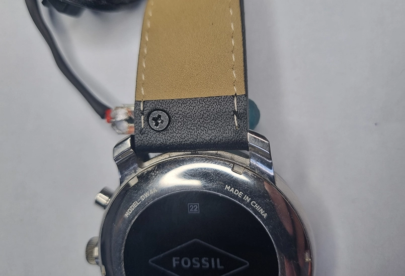
| 1 | Fossil Q Explorist watch |
| 1 | Leather watch band |
| 1 | Double CR2032 battery holder |
| 2 | CR2032 3v batteries |
| 2 | M3 x 3mm countersunk screws |
| 1 | M2 x 4mm countersunk screw |
| 1 | GL5537 Photoresistor |
| 1 | 5mm blue LED diode |
| Facer.io mobile app | |
| Metro 2033 "Last Light - CMD" watch face (free) | |
| 2 | Flat spade connecters |
| 1 | 3D printed model of LED enclosure |
| 100mm | 30awg wire |
| 40mm | 3mm heatshrink tubing (optional) |
| Hot glue | |
| Superglue |
Step 1: Set up the watch
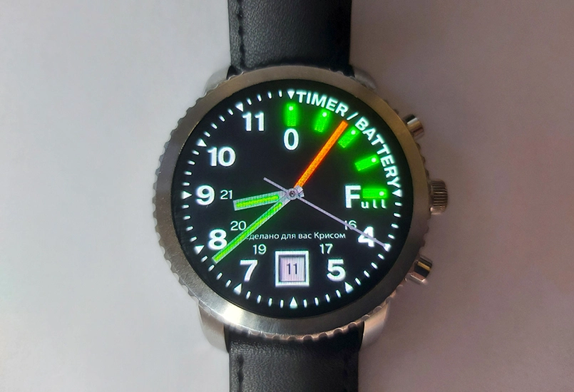
The Fossil Q Explorist Gen 3 Smartwatch was used as it is the closest match to the actual Metro analog watch. These smart watches are quite cheap second-hand. Any round smartwatch will do. A watch compatible with the Facer.io mobile app is recommended as it provides a free Metro 2033 watch face. Facer.io works with Android phones, Google WearOS and Tizen. Facer.io also works with Apple, but most Apple watches are square-faced and therefore not suitable for a Metro watch. WearOS and Tizen provide many more options, with the Fossil Explorist being the closest match.
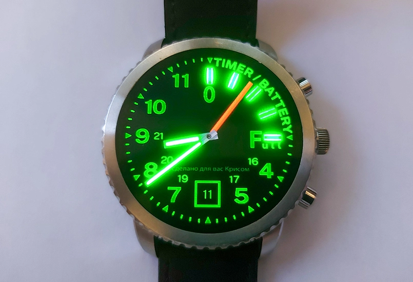
Simply connect the watch to a phone and search for “metro 2033” in the Facer app. There are a few different free versions to choose from and after trying a few out, the Last Light - CMD version was selected. It also includes a night time all green look.
The project could stop at this point, resulting in a convincing Metro-style watch. The following steps take it closer to the in-game version.
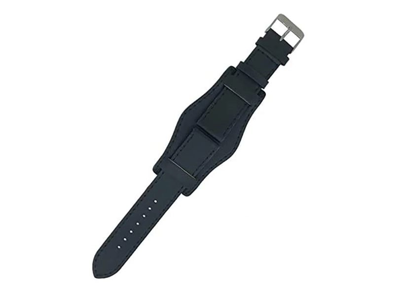
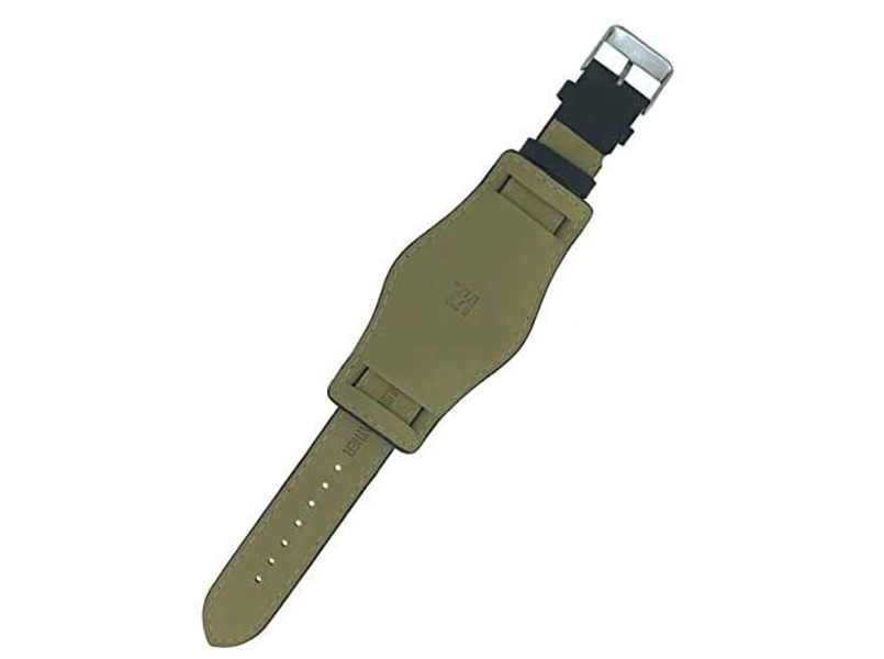
Step 2: Watch strap
The actual watch strap in the game is a little unclear and some versions of the watch are seen worn on a forearm bracer. For this project, a military style wide black leather watch strap was chosen. One was sourced online and includes the watch pins. The Fossil Explorist requires a 22mm wide strap and these are easy to fit.
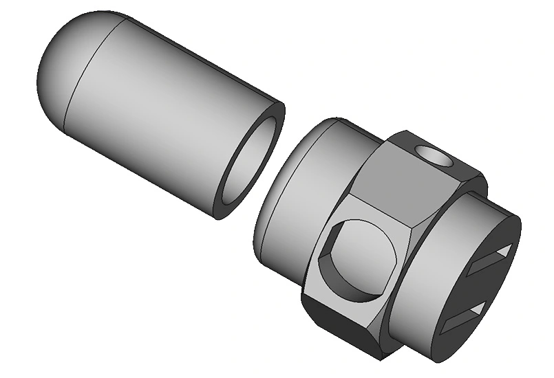
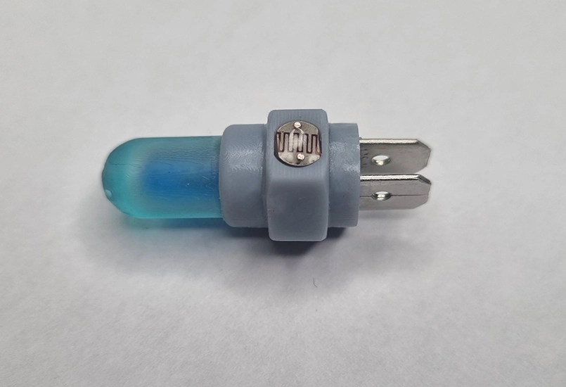
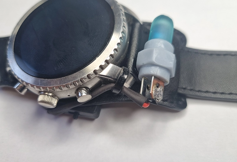
Step 3: Light detector - 3D model
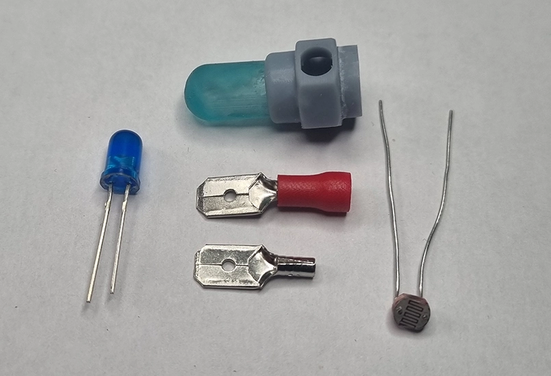
This is where the watch is taken much closer to the actual Metro watch. The light meter consists of a 3D model, blue LED, photoresistor and a battery.
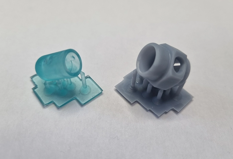
The 3D model is in two parts: the LED holder and the main body which sits at the top of the watch.
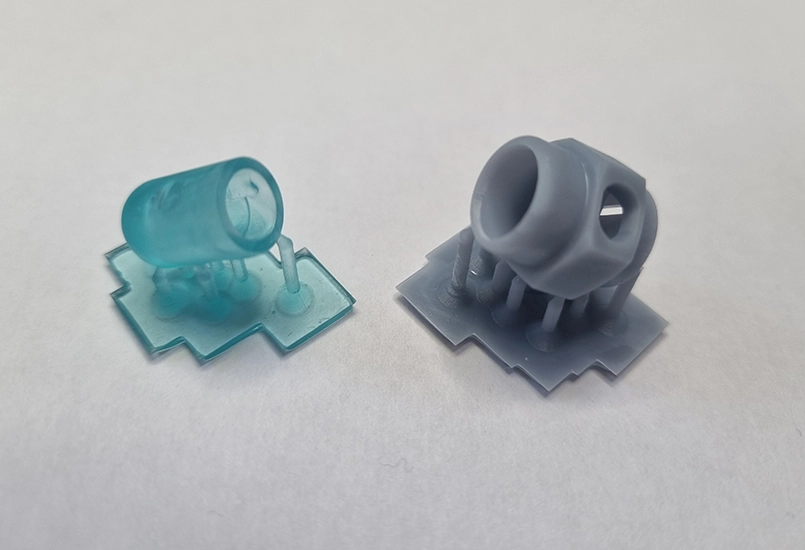
Ideally the 3D model should be printed on a resin printer as the parts are small with some detail. The body can be printed on a traditional FDM filament printer, but a very fine layer height is recommended.
Light grey resin was used for the main body and transparent blue for the LED holder. If transparent blue resin is not available, clear transparent resin with a small amount of resin pigment mixed in can be used.
If neither a resin printer nor transparent resin is available, the 5mm blue LED can be replaced with a larger 10mm blue LED.
There are three versions of the LED mount model. Two versions include a small hole at the back to screw it to the leather watch strap. The other version has no hole and can be zipper-clipped to the watch or glued in place. See Step 6.
You can download these STLs for free from my Cults3d.com page.
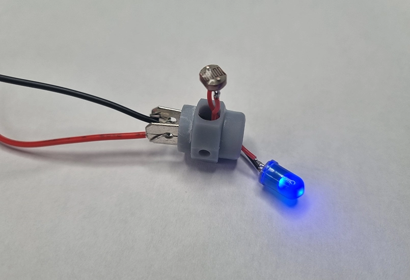
Step 4: Wiring the components
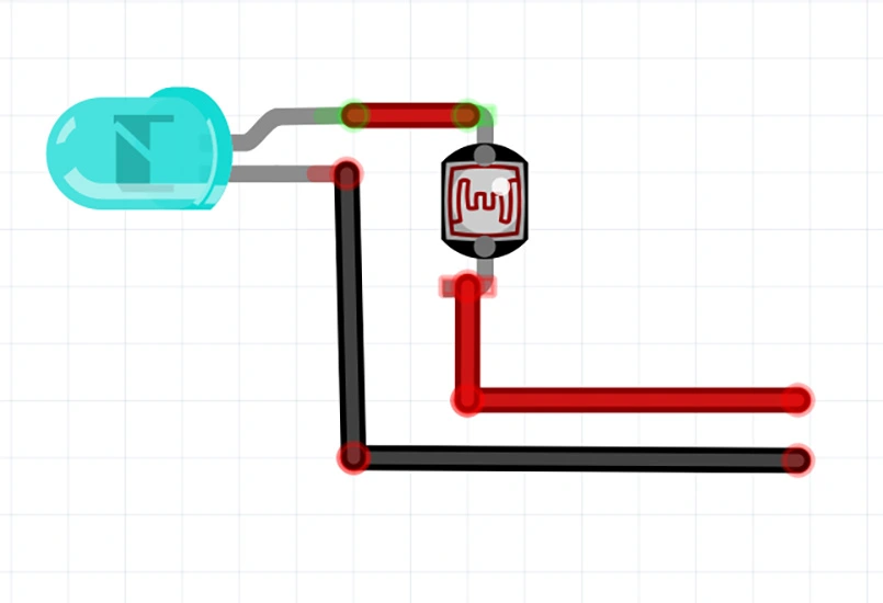
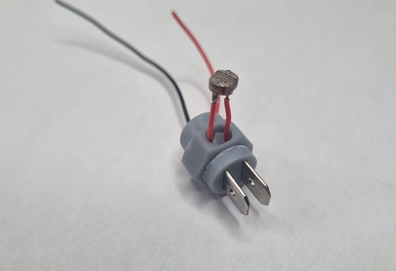
This is the fiddly step, as everything is quite small. For this step the blue LED is wired to the photoresistor and then to the spade terminals.
The tricky part is getting the assembly into the housing. If the LED pins are soldered directly to the photoresistor pins and then directly to the spade terminals, fitting everything together becomes difficult. Instead, cropping the component pins to the minimum comfortable soldering length is recommended. Super flexible 30awg silicone insulated wire can then be used to hook everything up. This provides insulation to prevent shorts and offers flexibility when fitting everything inside the 3D printed enclosure.
The order used was:
The photoresistor is a tight fit and is best pushed through from the top, using a hard surface such as a tabletop to press it flush with the body.
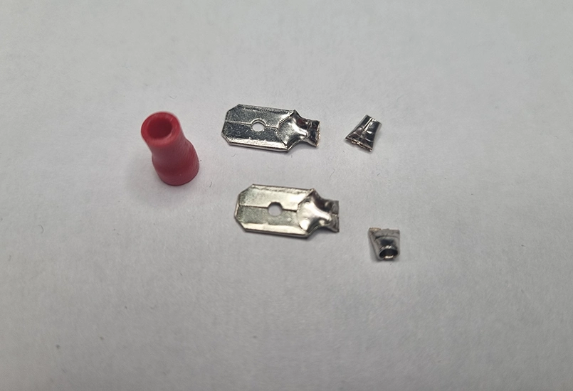
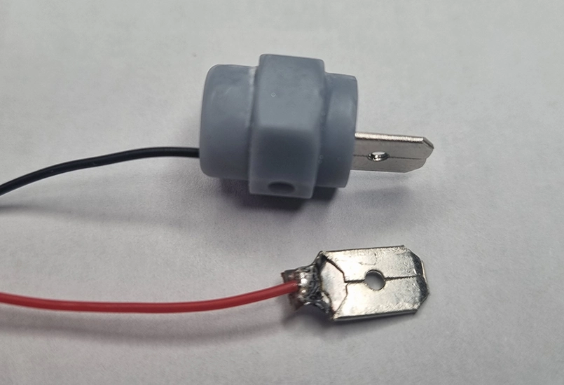
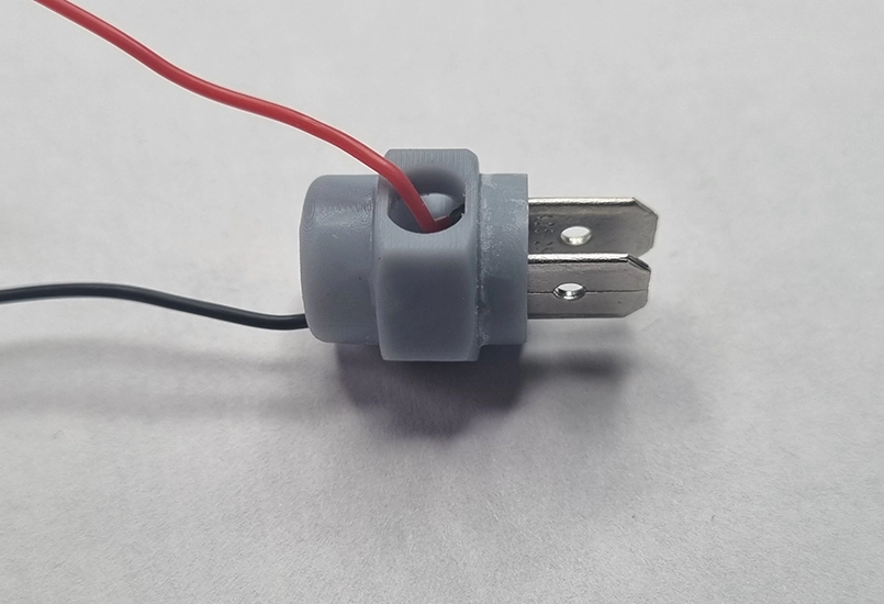
The spade terminals used are 1mm thick by 6mm wide. The original sheath was removed, the wire end cropped short, and then soldered.
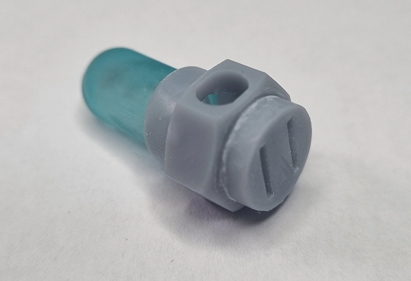
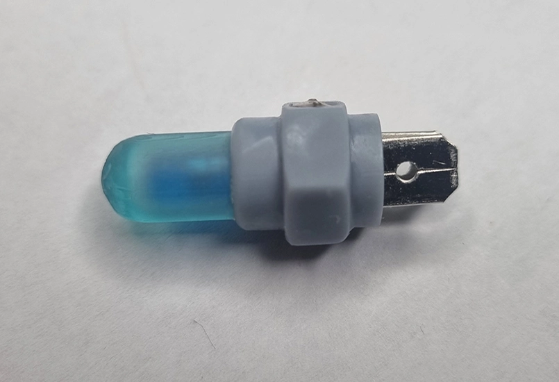
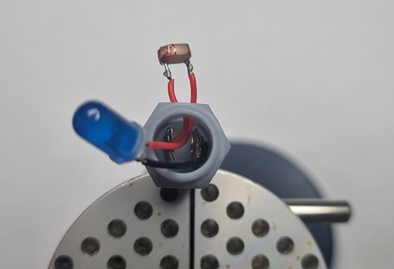
The LED holder can now be assembled to the main body. Gluing should be avoided at this stage until testing is complete. It is also important to keep track of which spade terminal is positive and which is negative.
The LED and photoresistor should be tested with the battery before final assembly. Once confirmed working, a drop or two of hot glue can be placed in the bottom of the main body to hold the spade terminals straight and in place. No glue is required for the photoresistor due to the tight fit. Finally, a small amount of superglue can be used for the LED holder.
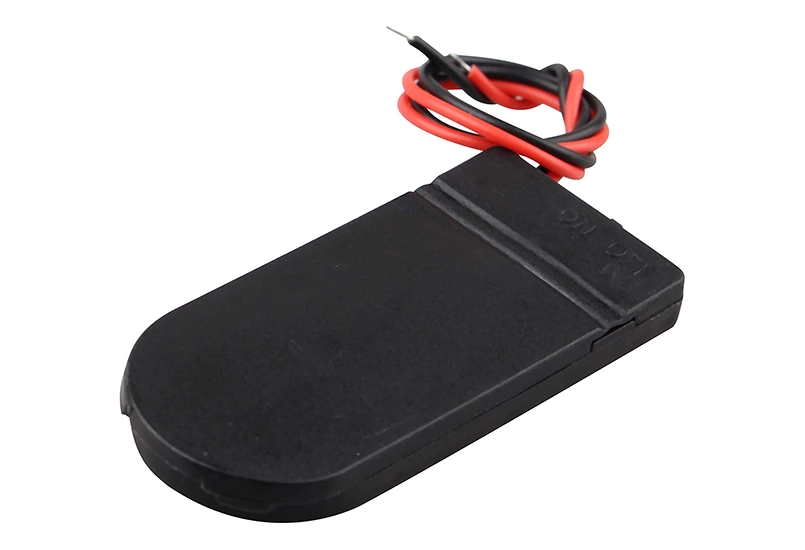
Step 5: Adding power
Power is added completely separately from the watch itself.
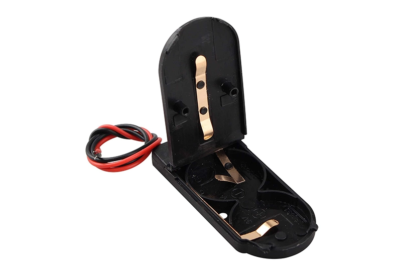
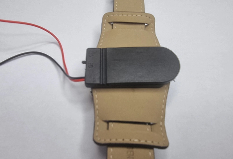
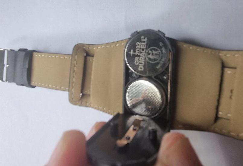
Two CR2032 button batteries are used in a slim holder that includes an on/off switch. These are inexpensive and commonly available.
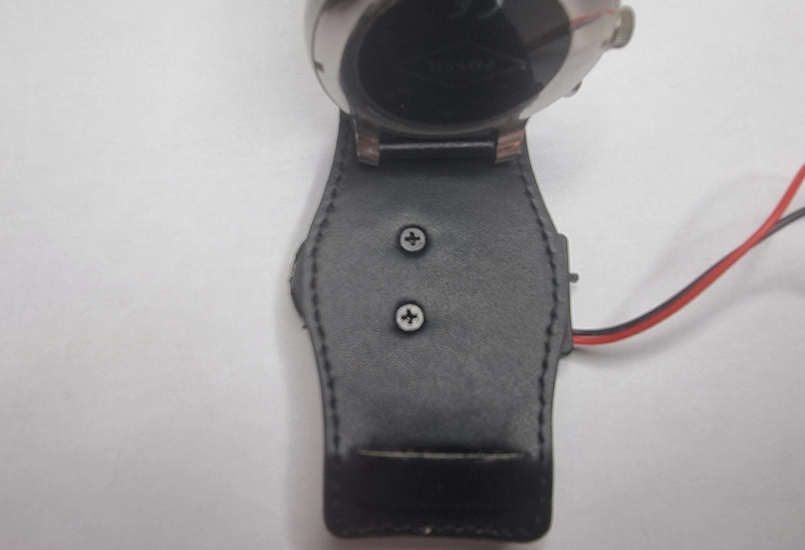
The double battery holder is mounted to the back of the watch strap. The strap is flipped over, the two holes marked, and a small hole carefully punched through the leather. A pair of M3 x 3mm countersunk screws are then used to attach the battery holder to the strap.
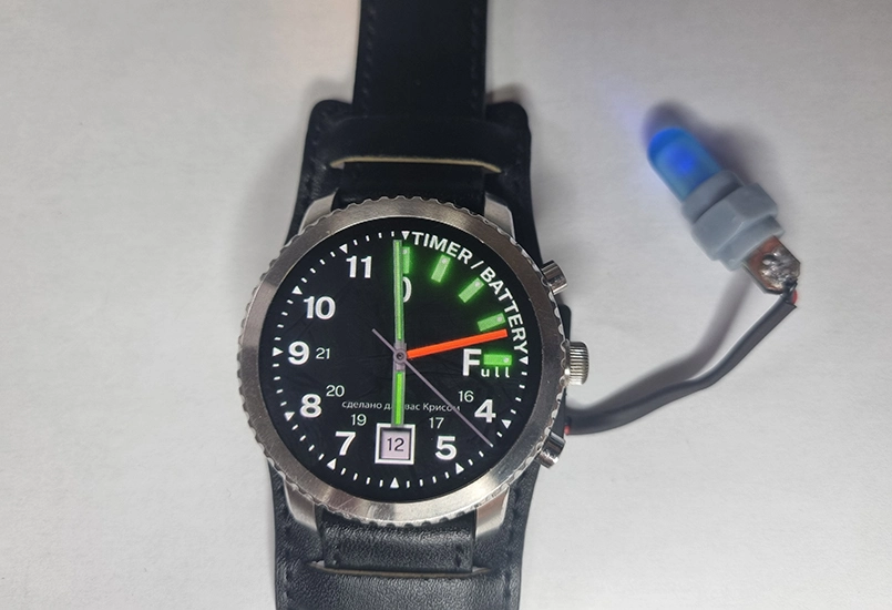
The battery wires are trimmed to length and covered with 3mm heatshrink tubing. With polarity noted, the wires are soldered onto the spade terminals. Once switched on, the LED should illuminate in normal light conditions. Placing a finger over the photoresistor should cause the LED to turn off. LED brightness is determined by the amount of ambient light detected by the photoresistor.
If it does not appear to be working, the CR2032 battery orientation should be checked. One battery is installed positive side up, and the other positive side down.
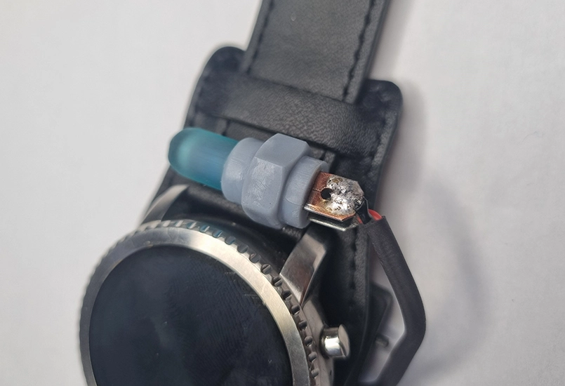
Step 6: Fixing the light meter to the watch
If everything is working correctly, the light meter can now be fixed above the main watch face. Several options are available.
The part can be glued or zipper-clipped in place. Hot glue is typically not strong enough, so superglue is recommended. Care should be taken to ensure the glue does not interfere with the strap pins.
A version of the 3D model with a small M2 mounting hole can be used. A small hole is punched through the leather strap and the light meter secured using an M2 4mm screw. On the first attempt, strap curvature caused the photoresistor to face too far backwards and become partially obscured.
A revised version of the light meter with a different hole position places the photoresistor in a better position. Testing the different models is recommended to determine the best fit.
The final step is to zipper-clip the battery wire to the side of the watch to keep everything snug.
Switch the unit on and give it a test. In normal light conditions the LED should illuminate. Placing a finger over the photoresistor should cause the LED to turn off. LED brightness is determined by the amount of ambient light detected by the photoresistor.
If it does not appear to be working, check the CR2032 battery orientation. One battery is installed positive side up and the other positive side down.
The final step is to zipper-clip the battery wire to the side of the watch to keep everything snug.
Job done! The result is a unique and very cool Artyom Metro 2033 watch.
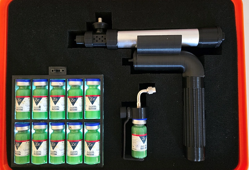
Replica of the injector device from the Metro 2033 game (Exodus DLC), built using 3D printed parts and electronics.
Read more